Kinematic Self-Replicating Machines
© 2004 Robert A. Freitas Jr. and Ralph C. Merkle. All Rights Reserved.
Robert A. Freitas Jr., Ralph C. Merkle, Kinematic Self-Replicating Machines, Landes Bioscience, Georgetown, TX, 2004.
3.18 Moses Self-Replicating Construction Machine (1999-2001)
During 1999-2001, Matt Moses, a graduate student in the Department of Mechanical Engineering at the University of New Mexico, invented a unique set of Lego-like blocks that are especially well-suited for the self-replication task and elaborated some of the detailed kinematic requirements of a machine that can self-replicate or assemble its own duplicate from a stock of components [915, 1159]. The Lego-like components were plastic parts that were cast from a polyurethane resin and then used to make a 3-axis Cartesian manipulator which was subsequently shown to be kinematically capable of assembling a duplicate of itself. The machine cannot fabricate its own plastic components and – in addition to mechanical problems that hamper the physical device – the constructor must be controlled by an external entity. To be fully self-replicating, says Moses [915], the device would have to autonomously control its own actions and would have to possess the instructions necessary for carrying out its duplication. “The ultimate goal of this work is the creation of a machine that can automatically fabricate components from raw materials and then assemble these components into a wide range of useful devices, including duplicates of the original machine.”
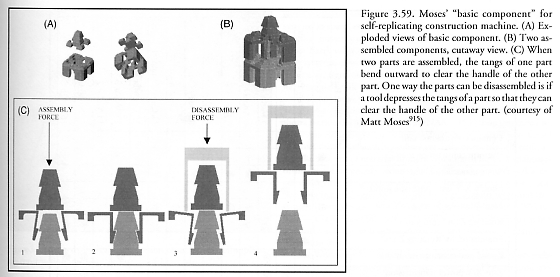
Figure 3.59(A) shows two exploded views of Moses’ “basic component.” The component consists of two parts – an upper “handle” and a lower “base”. The base contains four compliant snap tangs that are complementary to the four tapered surfaces of the handle. Blocks can be assembled together as shown in Figure 3.59(B), which also shows how the snap tangs of the base will grasp the undercut of the handle of another part. In addition, the convexly tapered surfaces of the base mate with concavely tapered surfaces of the handle in order to provide rigidity with respect to shear and torsion between parts. Most edges on the handle and base are chamfered. The chamfers are important because they allow a certain amount of positioning error during assembly. The tangs and handle also contribute to error tolerance, since they are tapered such that two parts need not be exactly positioned before assembly. The slots cut in each side of the base allow the part to be assembled onto other parts that have reinforcing segments. Depending on the type of loading on the tang, it will bend primarily in either the upper or lower segment of the ‘L’. This can be exploited so that parts can be disassembled. In other words, the snap-assembly is reversible. Figure 3.59(C) shows a sequence of sectioned views of two parts during assembly and disassembly.
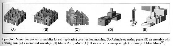
A plane surface can be tiled by the parts, resulting in a plane covered by periodically spaced handles. The constructing machine described here operates on such a plane. Part type 3 (green in Figure 3.60(A)) is identical to part type 2, except that its top handle has been replaced with a rotary handle. A second type of connection between parts is the handle-slider connection. The slider – a long beam with the same cross section as a snap-tang – allows a part to slide back and forth along the handles of other parts, as in Figure 3.60(B) which shows a rack assembled onto the operating plane. By adding an actuator, forces can be applied to moving parts and their positions can be controlled. In this component set there are two types of motors – a rotary type and a linear type. Racks are actuated by rotary motors. The rotary motors are made by attaching a basic part and a drive gear to an off-the-shelf motor. The rack and the drive gear have self-aligning teeth (the teeth easily mesh) in order to simplify assembly. In Figure 3.60(C), a motor has been added to the assembly.
Moses’ constructing machine is built out of 45 parts, including 11 different kinds of parts (all meticulously described in his thesis [915]), as follows: Rack (8 used in constructing machine), Motor 1 (1 used), Anchor (7), Rail (13), Cap (8), Rotary Cap (1), Cross-member (3), Cap with Support (1), Cross-member with Support (1), Motor 2 shown in Figure 3.60(D) (1), and Motor 3 shown in Figure 3.60(E) (1). Five other parts (Basic Part, Plane Element, Rotary Plane Element, Small Gear (11 teeth), and Large Gear (14 teeth)) are not used in the constructor but could be incorporated into devices that the constructor could assemble. Addressing tradeoffs in designing parts sets, Moses [915] explains: “These ‘universal’ components are not all that universal – some of the parts are used in large numbers, while other special-purpose components are used infrequently. It is possible that an optimally designed component set would contain only a few types of parts, and these parts would find more uniform use in an assembly. Keep in mind, however, that there is a tradeoff between the complexity of the set itself and the complexity of an assembly made from it. Making a given assembly from a set of simple components may necessitate the use of many more parts than would be required when making an equivalent assembly from a set that had an extra few special-purpose components.”
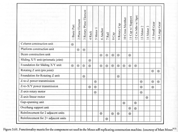
Moses continues: “The component set was designed in an iterative process. During this process, there was no clear design for the constructor. New functionalities were simply added to the set until the parts could be made into a suitable manipulator. This aimless wandering through design space is often time-consuming and costly. Suh [1160] presents a systematic approach to design wherein a hierarchy of functional requirements (what a system must do) and design parameters (how it will do it) are evaluated based on two axioms: (1) Maintain the independence of functional requirements. (2) Minimize the information content of the design (keep it simple). The functionality matrix (Figure 3.61) for the component set [makes] clear...that not all functional requirements are independent, and also that in some cases many parts satisfy the same requirement.” A functionality matrix can be used to compare structures, components, or features of a design with the functions they perform.
Moses’ self-replicating construction machine (Figure 3.62) is a 3-axis Cartesian manipulator made only from parts in the previously described component set that can assemble a wide variety of devices, including duplicates of itself. The machine is kinematically capable of grasping, manipulating, and placing all of the components required for constructing its own duplicate, including the hardware required to manipulate mechanical components but excluding the portion responsible for control. The constructor lacks any type of sensor or onboard control and so must be controlled either by a human operator or a sophisticated external controller. Construction activities include the retrieval of components from a storage site and their subsequent connection to an assembly or operating plane, but components must initially arrive at the storage site through the action of another entity – namely, a human operator. Moses [915] lists the entire sequence of 410 steps (specific operations) that must be executed by the construction machine in order to install each of the 45 parts in its replica, in proper order, proceeding from (A) to (D) in Figure 3.62.
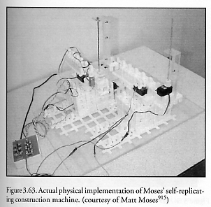
In the actual hardware implementation (Figure 3.63), constructor movements were sequenced by a human operator controlling the manipulator through a switch box. Moses candidly admits that “the idea did not work as well in reality as it did in simulation. In order to make a functioning constructor, some of the problems had to be solved by cheating – gluing certain parts together, for example. So the constructor and the device it constructs are not entirely identical. In many cases, the constructor could not develop the necessary force to assemble components. The necessity of strengthening the constructor with methods outside of the allowed fastening techniques can be eliminated in future iterations by producing parts of higher tolerance, revising the part set, or revising the constructor design. Problems with the boom could also be solved by revising the design of the constructor. A gantry-crane manipulator, where the boom is supported at each end, would avoid deflection problems and allow accurate placement of parts. Gantry-cranes are usually wrapped around their workspace, being larger than what they work on. This makes designing a gantry crane that can assemble a duplicate of itself difficult. The problem of running wires to the motors can be solved by laying conductive traces on the plastic parts.... While, kinematically, the design was capable of accessing and connecting the necessary parts to assemble a duplicate of itself, lack of stiffness due to the design of both components and manipulator prevented it from assembling its duplicate in reality.” Nevertheless, after an assisted replication both devices were operable.
Last updated on 1 August 2005