Kinematic Self-Replicating Machines
© 2004 Robert A. Freitas Jr. and Ralph C. Merkle. All Rights Reserved.
Robert A. Freitas Jr., Ralph C. Merkle, Kinematic Self-Replicating Machines, Landes Bioscience, Georgetown, TX, 2004.
3.28 Griffith Mechanical Self-Replicating Strings (2003-2004)
Saul Griffith [1312] (see also Section 4.1.5) is interested in the minimal logic required to exhibit physical self-replicating behavior, in the tradition of the Penrose block systems (Section 3.3). Griffith asserts that if the logical overhead is low enough, then self-replication has potential in a manufacturing sense. Griffith further constrains the problem to be addressed by requiring, first, that the self-replication should be arbitrary (i.e., the system can replicate a physical object of arbitrary complexity) and, second, that the replicated object should be able to conform to an arbitrary 2-dimensional or 3-dimensional geometry. Penrose completed his work at a time when state machines and the language to describe them were just being developed so it is not surprising that his description of his mechanisms offers no easily discernible blueprint for a more general logical design. The following material in this Section, describing a physical realization of a simple but general-purpose KCA self-replicating system, is largely excerpted from research notes generously shared with one of the authors (Freitas) by Griffith [1312].
A key aspect of Griffith’s designs is the memory requirement for replication. If each part of an assembly must retain the entire code for the assembly, then each part must have a memory capacity capable of storing that description. In biology, every cell does contain the entire code for the assembly, albeit at a coarser scale of assembly in the multi-tiered assembly design of biological entities, but at the subcellular level a different memory management scheme is used in which the “memory” is contained within the structure itself (i.e., the code within the base pairs of DNA). This localized copying/complementarity method can also be used in either 1-D (linear) or in 2-D (planar) nonbiological systems. A 1-D system will look very similar to DNA except that complementarity is not necessary and we can template an exact copy, not a compliment; a 4-base system is not strictly necessary because a 2-base (binary) system is sufficient. A 2-D, or planar, system would look like a programmed or templated “plating” type system. The difficulty in plating-type replication is in the termination signal, where the copy is to separate from the original to make way for a subsequent round of replication. Griffith [1312] observes that a 3-D system is not amenable to this replication treatment because not all of the structure is available at the surface of the assembly and therefore some of the information within the structure would need to be transferred (and stored in memory) through outer layers of the assembly. He notes: “It may be stating the obvious, but this is probably why biological replicating systems use linear assemblies for replication that can subsequently fold into 3-D structures (or unfold for replication).”
There are two ready approaches to basic replication, among others. In the first approach, the individual units of the assembly are state machines capable of selecting and copying similar units in a similar assembly. The biological analogy to this can be thought of as an RNAase-less RNA replication where the RNAase’s logical function of selecting and adding base pairs is performed by state machines within each base. In the second approach (more similar to biological systems), the logical machinery is the RNAase which assembles more basic units into a second RNAase, and so forth. These two approaches might be described as distributed logic replication and centralized logic replication. In the former, the logic requirements are performed by cellular automaton-type nearest-neighbor interactions between the cells. In the latter, the copying assembly (or RNAase equivalent) is the central processor that reads and copies the data tape. Griffith has concentrated his efforts on the distributed logic replication approach, in an attempt to design the minimal logical units for a replicating system capable of replication of an arbitrarily complex structure containing an arbitrarily complex string of assembly instructions. To represent the data string, Griffith uses two types of components which can be similar logically but must differ in some important way (e.g., shape selectivity) to enable subsequent processing.
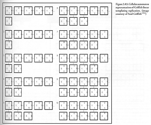
In his logic design for a parallel-replication 4-edge/3-neighbor system, Griffith uses a cellular automaton representation of the logical requirement for a linear templating replication. The diagram in Figure 3.83 shows the physical process of the replication. Each individual sub-unit or “cell” is represented as a box. A “1” represents an edge in an attractive state, attracting and binding random untethered cells. A “0” represents a neutral edge state where no binding will occur. A line between two cells represents a tethered bond – tethered bonds occur at the junction between any two edges in the “1” attractive state, such as “1 – 1”. A free floating unit cell is always in the (0, 0, 0, 0) state. A “1” edge will attract a “0” edge but not bind it. A “1” edge will bind to another “1” edge. “0” edges neither attract nor bond. The first steps in the replication are numbered from 1 to 10. Note that this system is replicating an original input string of 5 cells (in the upper row), but in fact scales to strings of arbitrary length.
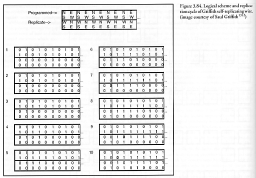
This mathematical representation employs the concept of cellular automata (Sections 2.1.3, 2.2, and 3.8). The self-replicating wire (Figure 3.84, topmost) is first filled with the initial values of the cells. The wire has 4 rows: the first two rows represent the cells of the original programmed string and the last two rows represent the replicating string. The orientation of the states of the cells is different for the programmed string and for the replication string. This is mainly because communication-intensive edges of neighboring cells must be arranged close to each other in order to keep the bits of each rule to a minimum. (This is convenient when mechanically implementing this design, wherein the geometry of the cell tiling is important in minimizing the number of states.) The topmost diagram in Figure 3.84 shows the actual orientation of the states of each cell – N stands for the state of the north edge, S for the state of the south edge, and so on. Notice that the division at the end of the replicating steps can be shown easily by simply dividing the wire horizontally in the middle: the top two rows will be the original programmed string and the bottom two will be the copied string. The quiescent space outside the wire is filled with 1’s. The updating of the wire itself is shown below. Each update is of one cycle, starting from the initial state.
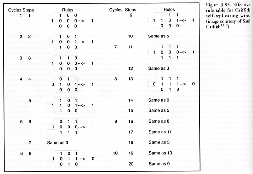
The effective rule table for Griffith’s replicating-string automaton is shown in Figure 3.85. Here, the “cycle” number refers back to each numbered image in Figure 3.84. There can be multiple logical steps at each cycle. In this rule table, the central value (second row, third column) is the one that’s changing in relation to its 9 neighbors (8 nearest neighbors and 1,2-distance neighbor to the left). This central value changes to the value indicated to the right of the arrow. While we typically conceive of a cellular automaton as a clocked updating of all cells at a regular interval, the scheme presented here is a self-clocking or “asynchronous” cellular automaton. Physically, this means that in a replicating system such as the original input string, which is floating in a bath of loose unbound cells, the clocking and logical operations occur upon the binding of a cell to the replicating string. It is important to note that the copying proceeds from left to right, and that at any given moment in the replication the replicating string is tethered to the input string by just a single bond at the site of the most recent cell addition. Note also that in cycle 8 the rules start to repeat. This is because the replication process can be arbitrarily long, but the general algorithm for updating the wire remains the same.
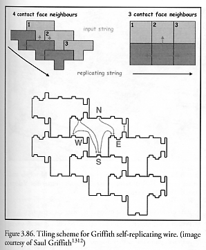
Since it is somewhat difficult to interpret the physical meaning of these rules simply by looking at the rule table, Griffith has built a physical mechanism that can execute this logic. One of the first choices in the design of this mechanism was the tiling scheme. The main constraint is that any logical operation should not be passed through another tile as that would require vias, memory, or logic within that cell. The logic designed above requires communication with 4 neighbors, so a tiling design enabling 4 contact-face neighbors and single-axis 4-neighbor contacts was desirable. Accordingly, the T-shaped tiles shown in Figure 3.86 achieve both goals – there are 4 contact-face neighbors, and all of those contacts can be executed on faces lying in one axis. The bottommost diagram in Figure 3.86 shows the logical routing. Arrowheads represent the opening of a gate for binding, while the origin of the line with the arrowhead represents the input connection that forces this change of state. The input of a connection can be thought of as routing a switch from a “0” to a “1” state (open for binding) at the arrowhead.
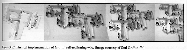
The first mechanical implementation of this design used LEGO® blocks with laser-cut custom parts in acrylic (Figure 3.87). The physical scale is roughly 3 x 4 inches for the whole cell (leftmost image). The three rightmost images demonstrate the replication sequence for a dimer. The blue and pink units display exactly the same logic as represented earlier. The only difference is a mechanical shape selectivity that prevents pink binding to blue, and vice versa. One can now see how a bit string of data can be replicated by such a system. Any arbitrary input string of pink and blue tiles can be replicated in the lower string. Note that at the completion of the final cell in the replicating string, the two strings automatically divide into two complete strings ready for the next round of replication. Note also that this system is very simple, representing only 5 discrete states. In late 2003, Griffith reported [1312] that further work then in progress would lead to more complex replicating string designs, the details of which would probably be published in 2004 as part of his Ph.D. dissertation.
The significance of this work is clear, says Griffith [1312]: “With such low costs for digital logic, why concern ourselves with minimal state machines for replication? Concerted engineering efforts over the last 50 years have reduced the cost of silicon-based digital logic to extremely low levels. Basic microcontrollers with a lot of memory (by replication standards) and fully Turing-complete are available for under $1 each; if packaging costs didn’t dominate as the size is shrunk, they could surely be even lower in cost. However, even at any finite [per-unit] cost of pennies, or fractions of pennies, objects comprising 106 components or more start to have significant cost. By reducing the complexity of the subunits to an absolute minimum, one can reconsider logic implemented by mechanical, chemical, or similar means. Babbage’s revenge! At the level of just 5-6 states per subunit, one can start to imagine mechanical or chemical finite state machines that make up the micro- (or potentially nano-) scale subunits for replicating more complex machines.”
Last updated on 1 August 2005