Kinematic Self-Replicating Machines
© 2004 Robert A. Freitas Jr. and Ralph C. Merkle. All Rights Reserved.
Robert A. Freitas Jr., Ralph C. Merkle, Kinematic Self-Replicating Machines, Landes Bioscience, Georgetown, TX, 2004.
Appendix B. Design Notes on Some Aspects of the Merkle-Freitas Molecular Assembler
Self-replicating, mechanical nanobots are simply not possible
in our world.
– Richard E. Smalley, September 2001 [14]
When a scientist says something is possible, they’re
probably underestimating how long it will take. But if they say it’s impossible,
they’re probably wrong.
– Richard E. Smalley, October 2000 [3115]
B.1 Geometrical Derivation of Assembler Dimensions
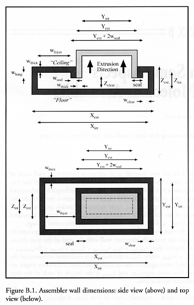
A preliminary design iteration revealed that the physical dimensions of the proposed molecular assembler are constrained by the choice of 4 box-specific geometrical parameters and 7 additional geometrical parameters related to the operation of the interior Stewart platform manipulators, the X-axis elevator upon which the manipulators ride, and the piston. Choosing a priori values for these 11 parameters establishes all remaining major physical dimensions of the system. In the following scaling analysis, the exterior physical dimensions of the proposed molecular assembler hull are (Xext, Yext, Zext) with enclosed exterior volume Vext = Xext Yext Zext and external surface area Sext = 2 (Xext Yext + Xext Zext + Yext Zext), and the internal physical dimensions of the assembler hull are (Xint, Yint, Zint) with enclosed interior volume Vint = Xint Yint Zint and internal surface area Sint = 2 (Xint Yint + Xint Zint + Yint Zint), using the coordinate system as defined by Figure B.1.
From simple geometry, Yext = Yint + 2wthick and Zext = Zint + 2wthick, where wthick is the external wall thickness; however, Xext = Xint + wthick because the fully extended piston replaces one wall. The minimum internal floor-to-ceiling clearance Zclear is limited by the underhang (whang) of the extrusion springs and the daughter device which is under construction, such that Zclear = Zint - whang. The desire to maintain adequate Y-axis clearance (wclear on either side of daughter walls) between the extruding daughter device and the parental XZ walls requires that Yint = Zext + 2wclear. To ensure that the base of each Stewart platform manipulator is square with equal Y and Z dimensions, we require that Zint = (1/2) Yint.
The derivation of Xint is driven by the interplay of three design choices involving the piston, the elevator, and the Stewart platform manipulators.
First, for the fully retracted Stewart platform manipulator to allow adequate clearance, we require that: Xint = xpiston + xpistonrod + xthrow + xelevator + xstrutseg + xchuck + xback + 2wextrusion + Yext + wclear, where xpiston is the piston plate thickness, xpistonrod is the minimum extension of the piston rod between the piston and elevator, (xpistonrod + xthrow) is the maximum extension of the piston rod between the piston and elevator, xthrow is the maximum possible piston throw during acoustic cycling between 1-4 atm driving pressure, xelevator is the elevator plate thickness, xstrutseg is the length of each of the two (nested) strut segments comprising each strut of the Stewart platform manipulator, xchuck is the height of the manipulator tool-holding chuck (excluding the length of various tool tips that might be grasped), xback is the distance between the extrusion springs and the most retracted possible position of the end of the tool chuck (allowing adequate clearance for a grasped tool tip), and wextrusion is the width of the extrusion springs.
Second, for the fully extended Stewart platform manipulator to reach the materials transport wall with the end of the tool chuck, we require that: xstrutseg + aext xstrutseg + xchuck = xscrew + 2wextrusion + Yext + wclear, where aext is the maximum fractional extension of the second strut segment that extrudes from (and is the same length as) the first strut segment, and xscrew is the length of each of the four elevator drive screws.
Third, to prevent solvent entry into the assembler interior, the piston must completely cover all four lines of elevator drive screw holes in the inside hull wall face. This requires that: xstrutseg + xchuck + xback = xpiston + xpistonrod + xelevator + xscrew.
Combining these three design constraints on Xint, then solving for Xint, yields the following relation: Xint = (Qscale + (3 + aext) Yext) / (1 + aext), where Qscale = (1 + aext) xthrow + (1 - aext) xscrew + (2 + 2 aext) xback + (2 aext) xchuck + (6 + 2 aext) wextrusion + (3 + aext) wclear. Taking wthick = whang = wclear = wextrusion = xpiston = xelevator = xchuck = xback = xscrew = 10 nm, xthrow = 15 nm (Section B.4.2), and aext = 0.75, then xpistonrod = 64.286 nm, xstrutseg = 74.286 nm for the first strut segment alone (e.g., a fully contracted strut), (1 + aext) xstrutseg = 130.000 nm for the fully extended Stewart platform two-segment strut, Zclear = 30 nm minimum floor-to-ceiling clearance, and so:
Zint = 40 nm, Zext = 60 nm
Yint = 80 nm, Yext = 100 nm
Xint = 323.572 nm, Xext = 333.572 nm
Vint = 1,035,430.4 nm3, Vext = 2,001,432.0
nm3
Sint = 84,057.28 nm2, Sext = 118,743.04 nm2
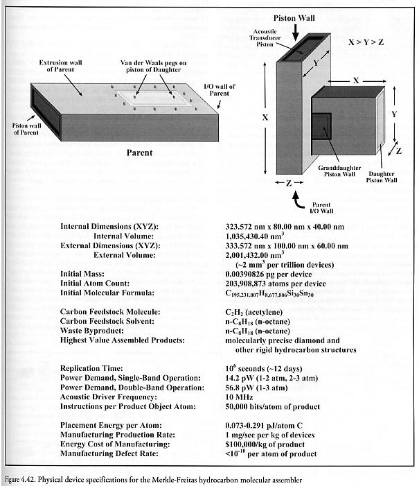
The density of the assembler is approximately rassembler = massembler / Vext = 1895.9 kg/m3, taking massembler = 3.90826 x 10⁻¹⁸ kg (Figure 4.42) and Vext = 2,061,432.0 nm3 (Table 4.2). This is significantly denser than the solvent density (rliquid = 702.5 kg/m3 for liquid n-octane), so in a g = 9.81 m/sec2 (1 g) gravity field the assembler will fall through the fluid from the top to the bottom of a reaction chamber of height Lchamber = 2 microns in a time tterminal = Lchamber / vterminal ~ 54 sec, where the particle terminal velocity vterminal is approximated by the Stokes sedimentation law [228] as vterminal = 2 g Lassembler2 (rassembler - rliquid ) / 9 hsolvent ~ 0.037 micron/sec, taking the mean assembler dimension Lassembler ~ 100 nm and solvent absolute viscosity hsolvent ~ 7.004 x 10⁻⁴ Pa-sec for n-octane at 273.15 K [3116].
In keeping with the goal of design simplicity, the proposed molecular assembler is constructed almost exclusively of hydrocarbon and pure carbon structures, and all products the molecular assembler is capable of manufacturing are similarly restricted. The great majority of the atoms in the assembler reside in its outer shell, because the interior of the device is mostly (~86%) empty space. The walls consist of solid diamond with a carbon atom volume number density ncarbon ~ 176 atoms/nm3 and all exposed surfaces are hydrogen terminated with a hydrogen atom surface number density of nhydrogen ~ 31.4 atoms/nm2. Excluding external adsorbates, the exact total atom count in the shell is NC,shell (~ ncarbon {Vext - Vint}) = 180,576,282 carbon atoms and NH,shell (~ nhydrogen {Sext + Sint + Spistonsides}) = 6,619,130 hydrogen atoms, where the hydrogen-terminated surface area around the piston plate at the end of its travel is Spistonsides = 2(2Yint + 2Zint) (xpiston) = 4,800 nm2. There are additionally NC,structure = 14,654,725 carbon atoms and NH,structure = 2,058,676 hydrogen atoms in all non-shell internal structures (Table 4.2), giving a total whole-device carbon atom count of NC,device = 195,231,007 carbon atoms and a total whole-device hydrogen atom count of NH,device = 8,677,806 hydrogen atoms. The device also includes exactly NSi,device = NSn,device = 30 atoms each of silicon and tin in mechanosynthetic tool tips (though subsequent work [2322-2325] suggests replacing Si and Sn with Ge) for catalytic purposes which must be supplied by a very small number of vitamin molecules in the feedstock, giving an exact total atom count of Ntotal = 203,908,873 atoms in the proposed molecular assembler, as detailed in Table 4.2. Note that ~92% of all atoms reside in the hull wall and piston plate structures.
Last updated on 13 August 2005